Acknowledgements: Often in an article that includes acknowledgements they are found at the end of the article. I am placing them at the beginning because I don't want anyone to miss them. Without the help of numerous people I have never met, I could not have written this article, and indeed, I would likely never have achieved the degree of accuracy in collimation of my newtonian reflector that I have sought.
In the modern world information is abundant and easily obtainable, but knowledge comes with much more difficulty. I acknowledge the invaluable assistance of:
- the contributors, moderators and sponsors of Cloudy Nights Telescope Reviews. This web site is a very important resource for amateur astronomers. I find the user forums especially valuable.
- Nils Olof Carlin, a Swedish amateur astronomer who I have never met. Nils has published numerous excellent papers on newtonian collimation and other astronomy topics on the internet, and his articles have helped me to understand the importance of collimation and the correct use of the various tools that are available.
- Howie Glatter, an American inventor and manufacturer whose laser collimation tools, in my opinion, are second to none in quality.
There are numerous tools available and many procedures documented for collimating newtonian reflector telescopes. The tools include sight tubes, cheshire eyepieces, autocollimators, single beam laser collimators, holographic laser collimators and barlowed laser collimators. The tools are available in 1.25" and 2" sizes to fit the commonly available amateur newtonian telescope focusers. One of the most commonly used tools is a combination sight tube and cheshire eyepiece. The qualities and prices of the tools vary widely. As for the procedures, some are quite simple and some are very complex - some are effective and some are not.
The need for accuracy and precision in Newtonian collimation depends partly on the focal ratio of the telescope. Faster focal ratios suffer more severe effects from poor collimation. The need for accuracy and precision also depends on your use of the telescope and on your tolerance for the errors that mis-collimation causes. For example, collimation errors may be more apparent in long exposure photographs made through the telescope than they are visually through an eyepiece.
My newtonian reflector is a 203 mm f/4.9, and I use it mostly for long exposure DSO photography with a digital SLR. When used for this purpose accurate collimation is mandatory. Occasionally I use it for planetary photography, with a barlow lens to increase the effective focal length and a small CCD imager that captures a very small field. While the small field of view and long effective focal length in this mode are more forgiving of collimation errors, the sharpness and fine detail desired for planetary imaging makes accurate collimation of prime importance.
At first I used a 1.25" combination sight tube/cheshire eyepiece to collimate this telescope, and I feel that I achieved the best collimation I could achieve with the tool. The biggest problem was that this telescope has an oversized secondary mirror, and the outline of the secondary mirror is not visible through the 1.25" combination tool even when the focuser is cranked all the way out. It is necessary to also retract the tool in the eyepiece holder considerably and clamp it in that position, in which position it wobbles significantly. So I never felt really confident that my alignment of the secondary mirror position, an important element in collimation, was as good as it needed to be.
Recently I purchased a 2" Howie Glatter Laser Collimator, with a 635nm laser, self-barlow attachment and holographic attachment. Included now with all of the Howie Glatter Laser Collimators is a 1 millimeter aperture attachment with a matte white face that can be used when the optional attachments are not in use.
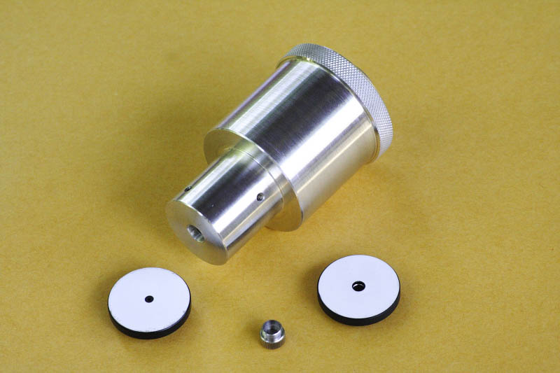
Figure 1 - the Howie Glatter 635nm 2"/1.25" laser collimator with attachments. Attachments (left to right): 1mm aperture, holographic attachment, self-barlow attachment. The 1mm aperture is included with all Howie Glatter collimators, but the holographic and self-barlow attachments are optional. All three attachments are threaded to screw into the face of the collimator, so only one attachment can be used at a given time.
While learning to use the collimator, at first I did not understand the instructions for using the holographic attachment to position the secondary mirror, and when I finally understood the instructions I found the procedure to be a lot of trouble with my solid tube newtonian. As a result I continued using the (too narrow) sight tube for that step in the collimation procedure, while using the laser collimator for the other steps. Ultimately I realized that I was still not achieving the desired collimation accuracy, because of the poor fit of the retracted sight tube in the focuser and because of the use of the 1.25" adapter during only one part of the collimation procedure.
I resolved to develop a repeatable process for collimating with the laser collimator alone, and to practice it until it became second nature. I have achieved that goal now and I have documented the procedure here.
- Square the focuser
The focuser should be "square" in relation to the OTA. In other words, it should be perpendicular to the OTA from all angles. Some focusers are collimatable, meaning that the tilt of the focuser can be adjusted, in a manner similar to the way the mirror tilts are adjusted, in order to square the focuser.
If your focuser is collimatable, it is a good idea to set it to the flat, un-tilted position before starting this procedure. If your focuser is not collimatable and is not square in relation to the OTA, you may shim it in order to make it square, but the penalty for not squaring the focuser is small, so you may choose to skip this procedure and proceed to the second procedure, adjusting the position of the secondary mirror. If you choose to shim your focuser, One way of doing it is to remove one or more of the screws that fasten the focuser to the OTA and reinstall them with one or more small flat washers between the focuser and the OTA. This procedure assumes that your focuser is collimatable, but lets you know when you need to shim the focuser if it is not collimatable.
This procedure requires removing the spider and secondary mirror from the OTA. Note that if your spider hub contains three collimation set screws (I believe this is the most common configuration), one (and only one) of those set screws should be positioned in line with the focuser axis when this procedure and the next procedure are performed. This requirement helps to assure that the secondary mirror holder ends up correctly aligned with the OTA axis.
Use the following procedure to test and adjust the squareness of the focuser:
- Remove the secondary mirror and spider assembly from the telescope.
- Crank the focuser out until the drawtube does not protrude into the OTA.
- Insert the laser collimator with the 1mm aperture into the focuser and turn it on.
- Use a ruler to measure the distance from the open end of the OTA to the laser beam on the focuser side.
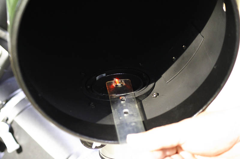
Figure 2 - Using a ruler to measure the distance from the open end of the OTA to the laser beam on the focuser side. - Use a ruler to measure the distance from the open end of the OTA to the laser beam on the side opposite the focuser.
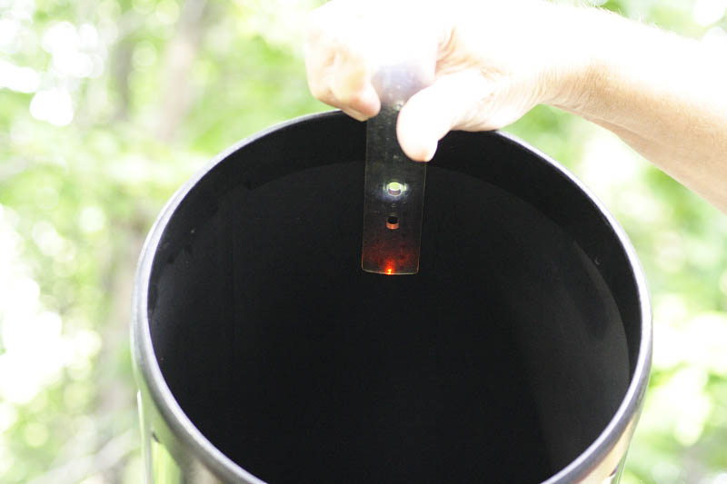 Figure 3 - Using a ruler to measure the distance from the open end of the OTA to the laser beam on the side opposite the focuser. The spider and secondary mirror need to be removed to make this measurement.
- If necessary, tilt the focuser so that the two measurements are equal.
- Back the collimation set screws out of the spider hub until they are recessed into the hub, and reinstall the spider (don't install the secondary mirror yet). Make sure that one of the collimation set screws in the spider hub is positioned in line with the focuser axis (see Figure 4 below).
- Adjust the spider so that the hub is centered in the OTA. Use a ruler or tape measure to assist with this adjustment.
- Standing in front of the OTA looking in towards the primary mirror, adjust the position of your head so that the spider vanes coincide with their reflections in the primary mirror.
- Holding this head position, put your hand, palm facing you, into the OTA behind the spider hub and at an angle so that the laser beam hits your hand.
- Look through the central hole in the spider hub (where the bolt that holds the secondary mirror goes) and verify that the laser spot on your hand is visible through the center hole and approximately centered in the direction perpendicular to the focuser axis. You may move your hand in order to see the laser spot, but maintain your head position as described. If the laser spot is not approximately centered in the direction perpendicular to the focuser axis, tilt the focuser in the direction perpendicular to the OTA's long axis in order to center it. Do not tilt the focuser in the direction parallel to the OTA's long axis.
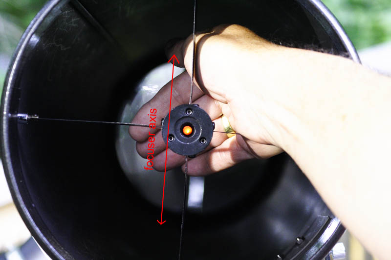
Figure 4 - Viewing the laser spot through the secondary mirror hub with the secondary mirror removed. This step facilitates squaring the focuser by adjusting its tilt perpendicular to the OTA axis. The spot should be centered in the direction perpendicular to the focuser axis, i.e., left and right in this photo. The focuser is located below the bottom of this photo.This photo also illustrates the correct orientation of the spider assembly, with one of the three adjustment set screws in line with the focuser axis.
- Remove the secondary mirror and spider assembly from the telescope.
- Adjust the position of the secondary mirror
The secondary mirror needs to be centered optically under the focuser. This adjustment is often made with a sight tube, but it can be made using the Howie Glatter Laser Collimator with the optional holographic attachment.
Keep in mind that "centered optically" in the case of the secondary mirror is not the same as "centered geometrically". Due to parallax, the optical center of the secondary mirror when it is tilted 45 degrees and seen as circular through the focuser drawtube is not at the geometric center of the mirror, so it is not possible to center the secondary mirror by marking its geometric center and using a single beam laser to adjust the position of the mirror until the laser beam hits the center mark.
In order to be centered optically, the secondary mirror needs to be offset towards the primary mirror, and ideally it should be offset away from the focuser by the same amount. This arrangement results in "fully offset collimation", and guarantees that the optical axis of the collimated telescope is exactly centered in the OTA. Setting the correct offset towards the primary mirror is easy - when offset correctly, the secondary mirror as seen through the focuser drawtube, from a point near the focal plane, will appear to be centered in the drawtube in the direction of the OTA's long axis, due to parallax. Setting the offset in the direction away from the focuser, however, is more difficult. Most modern collimation procedures forego this adjustment, resulting in "partially offset collimation". The effect of partially offset collimation is that the optical axis of the collimated telescope is not exactly coincident with the long axis of the OTA. The error, however, is small, and the consequences of the error are negligible for most purposes.
A word here about the importance of the distance from the collimator to the secondary mirror is appropriate. Due to parallax, the position of the secondary mirror's optical center as seen through the focuser depends on the distance of the observer's eye (or in this case the distance of the laser's holographic aperture) from the secondary mirror. The goal of collimation is to center the optical axis in the focuser axis in order to center the fully illuminated field in the observer's eye, or on the film or digital sensor for prime focus photography. Therefore the laser aperture should ideally be positioned near the viewing position, or near the focal plane for prime focus photography. It may be difficult to achieve this ideal position with a laser collimator without extending the focuser drawtube, but the penalty for not doing so is small. A slightly de-centered optical axis will likely not be perceptible through an eyepiece, and though it may be noticeable in long exposure prime focus photographs, the effect of uneven illumination in photographic images is easily corrected by the use of flat field frames. And with a focuser that is not perfectly square to the OTA, or one that shifts in alignment as the drawtube is extended, the misalignment caused by extending the drawtube far past the normal position or by adding an extension to the drawtube may introduce more severe collimation errors. You can determine how well your focuser's axis remains aligned when the drawtube height changes by noting the position of the laser spot on the secondary mirror, or on the inside wall of the OTA with the secondary mirror removed, when the focuser is extended and retracted. If it is reasonably stationary, perform the following procedure with the drawtube fully extended, or if a drawtube extension is used, position the drawtube so that the laser aperture is near the normal eye position, or near the focal plane for photography. If extending the drawtube causes the focuser axis to shift noticeably, perform the following procedure with the drawtube at approximately the height you will use for observing or imaging.
On my newtonian reflector the position of the spider hub can be adjusted by adjusting knurled nuts that attach the spider vanes to the OTA, loosening one knurled nut and tightening the opposite knurled nut, thereby moving the hub in relation to the center of the OTA opening. Other newtonian reflectors have different mechanisms for adjusting the position of the spider hub. If your spider hub position is not adjustable and the secondary mirror is not centered under the focuser in the direction perpendicular to the focuser axis, you will need to tilt the focuser to center it. This procedure assumes that your spider hub is adjustable, but points out when you will need to tilt the focuser if it is not adjustable.
Use the following procedure to adjust the position of the secondary mirror:
- Re-attach the secondary mirror to the hub and rotate the secondary mirror so that it is approximately facing the focuser. Tighten the center screw fully,so that the back of the hub is flush with the back of the secondary mirror holder.
- Insert the laser collimator with the 1mm aperture into the focuser and turn the laser on. Observe the position of the laser spot on the primary mirror. If it is not close to the center mark (it does not need to be exactly centered at this stage), use this procedure to center it:
- loosen the center bolt in the secondary mirror holder a couple of turns
- loosen each of the two secondary mirror adjustment set screws that are not in line with the focuser axis by 1/4 turn
- tighten the secondary mirror adjustment set screw that is in line with the focuser axis 1/4 turn
- tighten the center bolt in the secondary mirror holder fully, then back it off slightly so that the secondary mirror can be rotated
- rotate the secondary mirror until the laser spot on the primary mirror is in line between the focuser axis and the primary mirror center spot (see figure 7 below)
- adjust the secondary mirror tilt by loosing the set screw that is in line with the focuser axis and tightening the other two set screws equally until the laser spot on the primary mirror is close to the center mark
- Tape a piece of white printer paper into the tube about 1 foot from the secondary mirror position, between the secondary mirror and the primary mirror. The paper should block the tube so that you can't see the center of the primary mirror when looking into the OTA from the open end.
- Insert the laser collimator with the holographic attachment into the focuser and adjust the height of the focuser drawtube as explained above.
- Turn on the laser and observe the holographic pattern reflected onto the piece of paper. You will see the bright grid pattern within a circular, dimly illuminated field of diffuse light.
- Rotate the collimator in the focuser so that the grid pattern is parallel and perpendicular to the focuser axis.

Figure 5 - Viewing the holographic grid projected onto a piece of white paper taped into the OTA. The focuser is below the bottom of this photo. This step facilitates aligning the secondary mirror with the focuser axis. The grid should be centered in the diffuse red circle. In this photo, the grid is too high and too far to the left. Moving the grid down is accomplished by moving the secondary mirror towards the primary mirror. Moving the grid to the right is accomplished by moving the secondary mirror to the left or, if this is not possible, by tilting the focuser. - Center the grid pattern in the diffuse circle in the direction parallel to the focuser axis by moving the secondary mirror towards or away from the primary mirror. When moving the secondary mirror, loosen the large center bolt a few turns, then tighten each of the three set screws an equal amount and re-tighten the center screw. Check the grid pattern. Adjust more if necessary. Always turn each of the three set screws by an equal amount when making the adjustments so that the secondary mirror holder remains aligned correctly with the OTA axis. In the unlikely event that it is not possible to move the secondary mirror far enough towards or away from the primary mirror, you will have to tilt the focuser in the direction parallel to the OTA's long axis.
- If the grid pattern is not centered in the direction perpendicular to the focuser axis, you will need to adjust the spider hub position in the direction perpendicular to the focuser axis. If your spider is not adjustable or you don't have enough adjustment available, you will have to tilt the focuser in the direction perpendicular to the OTA's long axis.
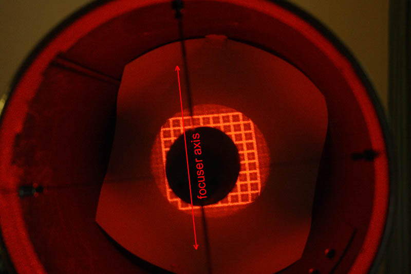
Figure 6 - Viewing the holographic grid projected onto a piece of white paper taped into the OTA. The focuser is below the bottom of this photo. In this photo the secondary mirror position has been adjusted, as described in steps g and h above, to center the holographic grid in the diffuse red circle. The secondary mirror is now correctly positioned, centered optically under the focuser. - Remove the paper taped inside the OTA. Remove the holographic attachment from the laser and attach the 1mm aperture. Insert the laser collimator back into the focuser. Turn the laser on and observe the position of the laser spot on the primary mirror. If it is very close to the center, intentionally mis-adjust it by loosening the two set screws that are not in line with the focuser axis by an equal amount (try 1/4 turn) and tightening the third set screw so that the laser beam strikes the mirror away from the center spot. It is important in this step to loosen the two set screws by the same amount in order to assure that the secondary mirror holder will be aligned correctly with the OTA axis at the end of the next procedure. Be sure all three set screws are tight when you finish this step.
- Loosen the center bolt in the spider hub and rotate the secondary mirror until the laser beam strikes the primary mirror on a line defined by the center of the focuser axis and the center of the primary mirror (see Figure 7 below). If you have followed this procedure carefully, this step assures that the secondary mirror is rotated correctly and that it's face is perpendicular to the focuser axis.
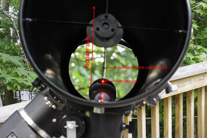
Figure 7 - Viewing the laser spot on the primary mirror. In this photo, the secondary mirror tilt has been carefully mis-adjusted in the direction parallel to the focuser axis, and the secondary mirror has been rotated so that the laser spot is in line with the focuser axis and the primary mirror center mark. This step assures that the secondary mirror is rotated correctly to face the focuser.
- Adjust the tilt of the secondary mirror
If you have followed the previous procedures correctly, the secondary mirror is now optically centered under the focuser and rotated so that it faces the focuser. Now the tilt of the secondary mirror needs to be adjusted so that the originating laser beam strikes the primary mirror precisely at its center. This adjustment can be made with a sight tube or with a correctly aligned laser collimator. The Howie Glatter Laser Collimator with the 1mm aperture installed provides a means of making this adjustment very precisely.
If a large adjustment is needed in this procedure, the position of the secondary mirror relative to the focuser axis, established in the previous procedure, may change. After this procedure it is advisable to return to the previous procedure and check the position of the secondary mirror using the laser collimator with the holographic attachment. If re-adjustment of the secondary mirror position is needed, repeat this procedure after making that adjustment.
Use the following procedure to adjust the tilt of the secondary mirror:
- Crank the focuser all the way in.
- Insert the laser collimator with the 1mm aperture into the focuser.
- Adjust the tilt of the secondary mirror by loosening one set screw and tightening another, in small increments, until the laser beam hits the center of the primary mirror's center mark and all set screws are tight. Do not loosen the central bolt during this procedure, and be sure to adjust the set screws in pairs and in small increments, loosening one and tightening another, to prevent the secondary mirror holder from rotating.
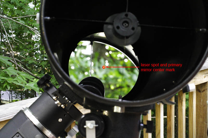
Figure 8 - Viewing the laser spot on the primary mirror, with the 1mm aperture installed in the laser collimator. In this photo, the secondary mirror tilt has been adjusted so that the laser beam strikes the primary mirror at the center mark. - Remove the laser collimator from the focuser and observe the secondary mirror through the focuser drawtube. If you have followed these procedures carefully its face should appear circular, indicating that it is rotated correctly to face the focuser. If it does not appear to be circular, loosen the center bolt in the primary mirror holder and carefully rotate the secondary mirror until the face appears to be circular. You will then need to repeat the second procedure, adjusting the position of the secondary mirror, and then repeat this procedure.
- Adjust the tilt of the primary mirror
The tilt of the primary mirror needs to be adjusted so that its optical axis is aimed precisely at the optical center of the secondary mirror. Performing this adjustment may result in enough movement of the primary mirror so that the reflected laser beam no longer strikes the primary mirror at its center mark. Therefore, it is advisable to return to the previous procedure, adjusting the tilt of the secondary mirror, upon finishing this procedure, and then to repeat this procedure. In worst cases several iterations of these last two adjustments may be necessary.
The tilt of the primary mirror can be adjusted using a single beam laser collimator, a cheshire eyepiece or a barlowed laser collimator. The single beam laser collimator, while accurate enough for many purposes, lacks the precision of the other two methods and relies upon the laser collimator being precisely collimated and exactly centered in the focuser. The cheshire eyepiece is less sensitive to errors resulting from imprecise alignment of the tool in the focuser. The barlowed laser method is quite insensitive to errors resulting from imprecise alignment of the tool in the focuser. The Howie Glatter Laser Collimator with the optional self-barlow attachment provides an excellent means of making this adjustment very precisely.
As mentioned previously, all new Howie Glatter Laser Collimators now ship with a 1mm aperture attachment having a matte white face. The primary benefit of the 1mm aperture is that it produces a tighter, circular laser spot that is easier to center than the oval spot normally produced by laser collimators. A secondary benefit is that the aperture diffracts the laser beam and produces a diffraction pattern, similar to the Airy Disk pattern seen in a focused star image at high magnification. In low light, this diffraction pattern acts like the diffuse pattern produced with the self-barlow attachment. When the beam hits the primary mirror center mark, it causes a diffuse beam containing the doughnut shaped shadow of the center mark to be reflected back to the secondary mirror and to the face of the collimator. This shadow can be used to achieve a parallax-free alignment of the reflected laser beam with the focuser axis, in the same way that the self-barlow attachment is used. The diffuse pattern produced by the 1mm aperture is, however, much fainter than the pattern produced by the self-barlow attachment, but in low light it is possible to use that pattern instead of removing the 1mm aperture and replacing it with the self-barlow attachment in step b below.
Use the following procedure to adjust the tilt of the primary mirror:
- With the laser collimator and 1mm aperture installed in the focuser, look into the OTA and observe the position of the spot formed by the returning laser beam on the secondary mirror, as seen reflected in the primary mirror. If it is not approximately centered, i.e., coincident with the spot formed by the originating laser beam on the secondary mirror, you need to perform a preliminary adjustment of the tilt of the primary mirror. Loosen the set screws and adjust the three adjustment screws on the primary mirror cell until the reflection in the primary mirror of the spot formed on the secondary mirror by the reflected laser beam appears very close to the spot formed by the originating beam on the primary mirror.
- Attach the self-barlow attachment to the laser collimator, re-insert it into the focuser and turn the laser on.
- Observe the position of the doughnut shaped shadow of the primary mirror center mark on the white face of the self-barlow attachment, using a hand-held mirror if necessary. On my 8" newtonian I can see the shadow from the front of the telescope, but I cannot get the camera in position to photograph it, so I had to use a hand-held mirror to make these photos. Adjust the three adjustment screws on the primary mirror cell until the doughnut shaped shadow is concentric with the laser aperture in the face of the self-barlow attachment. Tighten the set screws on the primary mirror cell and re-check the centering of the doughnut shaped shadow. If the shadow is no longer centered, loosen the set screws and repeat the adjustment. Don't forget to tighten the set screws upon completing this procedure.
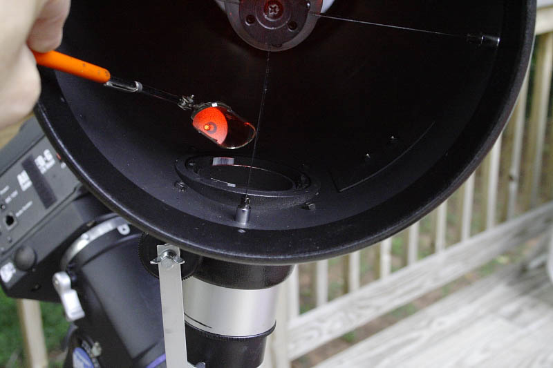
Figure 9 - Using a hand-held mirror to view the shadow of the primary mirror center mark on the face of the laser collimator self-barlow attachment. In this photo the laser aperture is not centered in the shadow - it is near the left edge of the shadow, indicating that the primary mirror is not tilted correctly.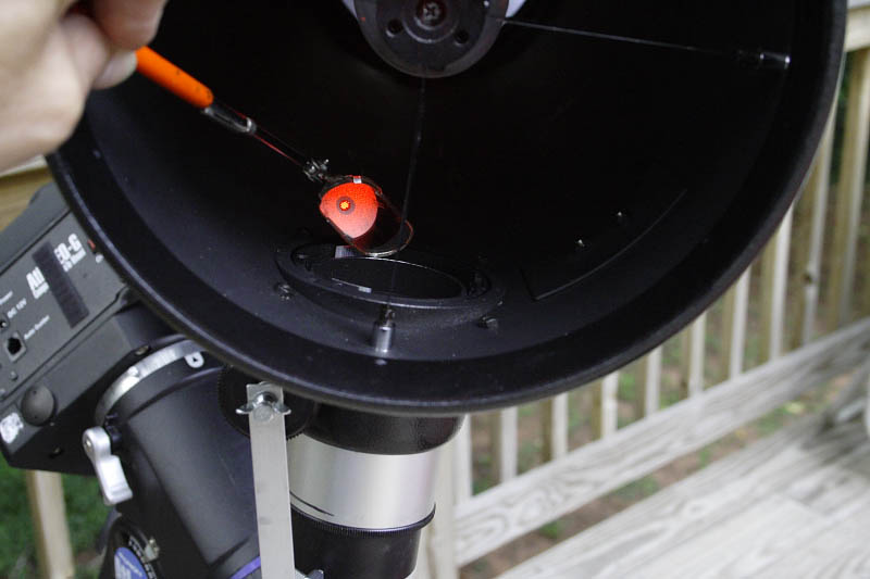
Figure 10 - Using a hand-held mirror to view the shadow of the primary mirror center mark on the face of the laser collimator self-barlow attachment. In this photo the laser aperture is centered in the shadow. The primary mirror tilt is correct adjusted.
- Perform a star test
The star test is the ultimate test of the collimation of a newtonian reflector. It must be performed on a night with good seeing, and after allowing ample time for equalization of the primary mirror temperature with the air temperature.
Focus the telescope on a fairly bright star (approximately magnitude 2 or brighter), using relatively high magnification (approximately 1 to 2 times the telescope's aperture in millimeters). Aim the telescope so that the star is exactly in the center of the field of view - if you have a reticle eyepiece, use it to assure that the star is centered. Verify that the diffraction rings associated with the Airy Disk are visible - this assures that the magnification is high enough and that the atmospheric conditions are stable enough for a meaningful star test. Defocus the telescope until a pattern of fuzzy, concentric rings surrounding a dark disk becomes apparent. Observe the symmetry of the pattern. The rings should be concentric with each other and with the dark disk, and all should appear perfectly circular.
Note that even when perfectly collimated the newtonian optical system still exhibits coma for off-axis stars, and depending on the telescope's focal ratio, the coma can be easily seen in the eyepiece at high magnification when the star is not precisely centered on the optical axis. Coma is evident in the star test as a non-symmetrical, comet-shaped ring pattern, with the tail of the comet pointing away from the optical center of the mirror. If your telescope is correctly collimated, you will not observe coma in the star test unless one of the following conditions is true:
- the star is not centered in the eyepiece field
- the eyepiece optical axis is not centered in the focuser's axis
- the center mark of your primary mirror is not in the optical center of the mirror
To prevent the first condition, perform the star test using an eyepiece with a cross-hair reticle to center the star.
The second condition could occur if you collimate your telescope with a 1-1/4" collimator and perform the star test with a 2" eyepiece, or vice versa. Unfortunately, using an adapter to hold your eyepiece or your collimator can significantly change the collimation. The solution to this problem is to obtain a premium quality focuser or to collimate and perform the star test with the same size eyepiece adapter.
The second condition could also occur if the weight of your eyepiece or your collimator causes the tilt of their optical axes to be different in the focuser. If your focuser can be adjusted to prevent this condition, adjust it. If not, consider obtaining a higher quality focuser.
The third condition may be more difficult to overcome. Start by verifying that the primary mirror center mark is exactly in the geometric center of the mirror. If it is not, replace it and re-collimate. If the center mark is in the exact geometric center of the mirror, your mirror's optical center does not coincide with its geometric center. In this event, it may be possible to identify the optical center of the mirror, replace the center mark at that point, and re-collimate. I will not attempt to explain that procedure in this document, however, and replacing the mirror is probably a better option.